Deformed Bar Anchors: Surface Profile, Welding Process and Selection Factors
Deformed bar anchors provide welded attachment points for industrial and concrete related assemblies. Selection depends on material, dimensions, loads and welding process.
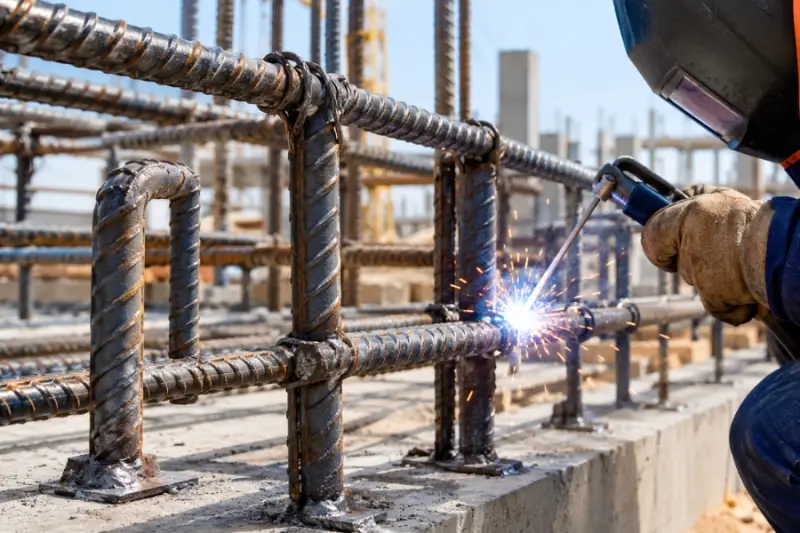
Deformed bar anchors combine a welded attachment point with a ribbed bar profile that can engage mechanically with surrounding material. Their practical value depends on the whole connection: the anchor dimensions, base material, welding method, expected loads and production conditions all shape the result.
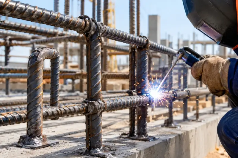
These anchors suit assemblies that need a bar style fastener for anchoring, reinforcement or load transfer. They appear in concrete related metal components, construction equipment, structural assemblies, industrial frames, heavy duty brackets, precast concrete applications and specialized anchoring systems. That range of uses makes product selection a design decision, not simply a matter of choosing a bar with the right appearance.
What the bar profile contributes
Ridges along a deformed bar create a more pronounced surface than a smooth bar. When the anchor is embedded in or otherwise interacts with a surrounding material, that profile can improve mechanical engagement and help resist movement. It can also support force transfer through the assembly.
The profile alone doesn’t establish connection capacity. Anchor material and dimensions, weld quality, base material and service conditions matter too. A suitable design therefore starts with the complete assembly and the forces it must handle, rather than treating the surface texture as a performance guarantee.
The anchor’s diameter and length depend on the job. One assembly may call for a particular bar diameter; another may need a different length or weld configuration. Manufacturers can set these details alongside material specifications and production requirements to avoid a mismatch between the component and its intended use.
Match the welding process to the assembly
Welding attaches the anchor to a metal base, so the process needs to suit both materials, their dimensions and the connection requirements. Two options discussed for welded fastening are capacitive discharge (CD) stud welding and drawn arc stud welding. They use different heat profiles and can fit different production needs.
| CD stud welding | Drawn arc stud welding |
|---|---|
| Uses stored electrical energy in a short cycle | Creates an arc between the stud and base material, with a controlled welding cycle |
| Localizes heat and often suits thinner sheet metal | Can introduce more heat and suit thicker base materials |
| Often fits smaller, lighter duty fastening and fast repetitive work | Can support heavier fastening, higher load requirements and deeper weld penetration |
| Can help limit heat exposure in thin material | Can provide stronger fusion for heavier materials |
| Depends on compatible studs, materials and careful surface preparation | Also depends on compatible materials, process parameters and controlled surface preparation |
| Can fit high volume production environments | Can fit heavy duty industrial welding applications |
These distinctions are starting points for evaluating a connection, not a universal ranking of methods. CD studs can support applications that need localized heat input; drawn arc methods can suit thicker materials and connections requiring deeper penetration. The selected process still needs to match the actual anchor, base material and production setup.
Northland Fastening Systems describes stud welding processes as an option for attaching an anchor to a suitable metal surface. Its information on CD studs covers applications where a short cycle and localized heat are relevant. Manufacturers should assess the full welding setup before choosing between them.
Selection starts with the base material and load
Before settling on an anchor, identify the base material and its thickness. Materials respond differently to welding energy and heat, which affects process compatibility. Then define the loads the finished assembly is expected to carry. Greater loads may call for a different combination of anchor dimensions, material and weld configuration.
Bar diameter and length affect fit, positioning and final performance. The chosen size should suit the application without adding unnecessary material or making installation harder. Weld compatibility belongs in the same review: the anchor, base material and process need to work together.
Production volume also matters. Repeated work depends on consistent positioning, equipment compatibility, cycle time and repeatable welding parameters. A process that works for a single assembly may need a different setup to produce dependable results across a larger run.
Keep production results repeatable
Surface preparation, alignment and process settings affect every weld. Clean the base surface appropriately for the selected process, since contamination can interfere with welding. Keep anchor positioning consistent so each part lands where the design requires it, and use validated parameters rather than making unnecessary adjustments during production.
Checking finished connections can reveal problems before they spread through a production run. The appropriate inspection or test depends on the application; no single procedure is specified for every anchor. Manufacturers should use checks suited to the connection requirements and the process they have selected.
Deformed bar anchors are a useful option when an assembly needs a welded bar style attachment with a profile that can engage with surrounding material. A reliable choice comes from reviewing the base material, anchor dimensions, weld method, loads and production workflow together. That assessment is what turns a promising component into a connection suited to its intended job.
 AMD Venice Uses 2.5D Packaging to Feed More Bandwidth Into EPYC Zen 6
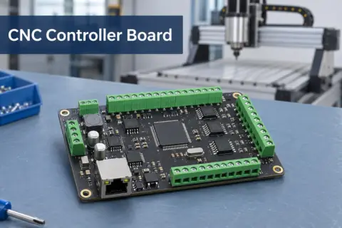 CNC Controller Board Design: Interfaces, PCB Specs and Assembly Testing
 Stratasys and Nano Dimension End $42.5 Million Markforged Sale Agreement