CNC Controller Board Design: Interfaces, PCB Specs and Assembly Testing
CNC controller performance depends on compatible interfaces, board construction and validation. A two-board assembly shows how copper and connector requirements shape production.
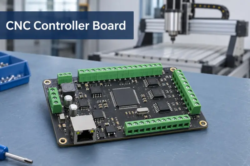
A CNC controller board sits between machine control software and the hardware that moves the axes, operates the spindle and reads sensors. Its practical value depends on more than its processor: signal types, connector layout, power distribution, PCB construction and assembly all have to match the machine. For equipment builders, those details determine whether the board set can be manufactured and integrated as intended.
EBest Circuit provides PCB fabrication, surface mount technology (SMT) and through-hole assembly, and inspection for CNC control electronics. The work can cover requirements from copper specifications to mating connectors. The company’s example of a stacked controller and driver assembly illustrates why a multi-board product needs coordinated fabrication and assembly planning.
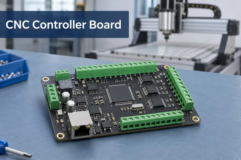
Controller outputs and motor drivers have different jobs
The motion controller determines when an axis should move and sends commands to its drive. The drive supplies the electrical power that produces motion. A Step/Dir output carries command signals; it does not connect directly to motor windings. Some products put controller and driver circuits on one PCB, while others use separate boards or external drives.
In a typical Step/Dir arrangement, the number of pulses sets commanded travel, pulse frequency sets requested speed, and a direction signal selects rotation direction. The driver translates those inputs into controlled winding currents. With a servo system, feedback may be handled within the drive or by a wider control system, depending on the architecture.
These arrangements carry different design and manufacturing considerations:
- Integrated controller and drivers: Logic, communications and motor power share one PCB. Driver packages and high-current paths sit alongside timing-sensitive circuits, so component placement, copper distribution and soldering requirements need to be considered together.
- Separate controller and driver boards: A logic board sends commands to another board or to external drives. The boards can have different copper specifications, but their pinouts, alignment and mechanical spacing must match.
- PC-connected motion hardware: A host computer provides the interface and some control software, while dedicated hardware handles time-sensitive motion outputs. The board’s communication method and software support need to suit the host system.
The label “breakout board” doesn’t fully describe a product’s function. Some boards simply distribute or condition signals; others include a motion processor. Circuit architecture and supported functions are more useful selection criteria than the label alone.
Match the interfaces to the machine
Axis count describes only part of a controller’s capabilities. The electrical characteristics of its inputs and outputs, along with firmware support, determine how it can connect to drives, sensors and accessories.
| Interface | Typical function | Compatibility detail |
|---|---|---|
| Axis drive outputs | Step, direction and drive enable | Single-ended and differential outputs require matching receiver connections. |
| Limit, home and probe inputs | Travel detection, machine referencing and tool contact | Dry-contact, logic-level and industrial-voltage signals need different input circuits. |
| Spindle interface | Run command and speed reference | Relay contacts, PWM and 0–10 V analog signals are distinct output types. |
| Encoder inputs | Position or speed feedback | Signal format and receiver bandwidth must suit the encoder. |
| Auxiliary outputs | Coolant, relays and other accessories | A logic output may need an external power-switching stage. |
| Host communication | Command and machine-status transfer | USB or Ethernet connectivity alone doesn’t establish software compatibility. |
A 3 axis CNC controller board may have enough motor channels for a dual-motor gantry, or it may need another channel. Conversely, a fourth motor output doesn’t necessarily support an independently interpolated fourth axis. Motor-channel count and supported machine motion are separate specifications.
An Ethernet connector also represents more than a socket on the PCB. Magnetics, protection parts, routing and connector grounding all affect the interface. Assembly details matter too: orientation and the specified mating parts must be correct, or the harness may not fit even when the board is populated properly.
Noise control begins with the current paths
Spindle drives, motor cables, contactors and switching supplies can disturb low-level signals, especially when signal wiring runs alongside power wiring. Board design reduces the paths by which unwanted energy enters a circuit and gives signal currents a suitable return path.
Isolation can separate electrical domains, but an isolator by itself does not create a complete isolation barrier. The power arrangement, PCB clearances and connections across that boundary matter as well. Differential signaling can reject common-mode noise when its transmitter, receiver, cable and termination are designed to work together.
- Preserve signal return paths. Routing fast signals over a suitable reference plane helps limit loop area. Plane splits can force return currents onto longer routes.
- Place protection at external connections. Filtering and protection components address disturbances entering through cables. Substituting parts can change electrical behavior or create footprint-fit problems.
- Separate sensitive circuits from switching currents. Motor-current paths and analog spindle references should not share poorly controlled returns. Increasing copper weight alone won’t resolve unwanted coupling.
- Make physical connections reliable. Connector polarity, terminal seating and solder joints help preserve the intended circuit during normal installation and service.
Board inspection can check the assembly, but it cannot establish the machine’s full EMC performance. Enclosure design, cable routing, grounding and connected equipment also affect system behavior, so board checks and machine-level validation answer different questions.
Fabrication ranges need to be assessed as a combination
EBest Circuit lists FR4 fabrication options for control boards and supports SMT and through-hole component assembly. A logic board, a driver board and a combined design may have different requirements. Copper weight, trace geometry, routing density and stack-up need to be considered together.
| Fabrication item | Listed process range | Special process or condition |
|---|---|---|
| FR4 layer count | 1–10 layers | 10–32 layers subject to special-process review; high-Tg material for builds of 8 layers and above. |
| FR4 material Tg options | 130–140°C, 150°C, 170–180°C | Selection follows the stack-up and thermal requirements. |
| Outer-layer copper | 1–5 oz | Higher weights need separate review of geometry and process. |
| Outer-layer trace/space at 1 oz | 4/4 mil | 3/3 mil special process. |
| Outer-layer trace/space at 2 oz | 8/8 mil | 6/6 mil special process. |
| Minimum finished hole diameter | 0.20 mm | 0.15 mm special process. |
| Through-hole aspect ratio | Up to 8:1 | Up to 10:1 special process. |
| Plated through-hole diameter tolerance | ±3 mil | ±2 mil special process. |
| Board thickness with ENIG finish | 0.4–3.5 mm | Available combinations depend on layer count and stack-up. |
| ENIG deposit thickness | Gold 0.025–0.125 µm; nickel 3–8 µm | Specified within fabrication requirements. |
These figures describe process ranges; they don’t mean every listed extreme can be combined in one build. The 1 oz trace/space values, for example, don’t automatically apply to a 2 oz driver board. Tg is a material transition temperature, not a continuous operating-temperature rating for a finished board.
Assembly options include SMT reflow, through-hole soldering and selective wave soldering. A CNC control PCB may combine small integrated circuits and passive components with tall terminal blocks, relays and communications connectors. Their different thermal masses, access requirements and temperature limits affect the assembly sequence.
Solder paste inspection (SPI), automated optical inspection (AOI) and X-ray inspection serve different purposes. The appropriate approach depends on the components and the build. Layout and package choice help determine whether inspection of hidden joints is useful.
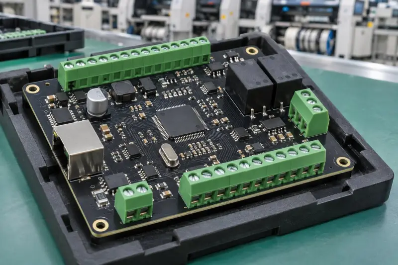
A stacked controller and driver assembly
EBest Circuit describes a two-board CNC controller assembly for entry-level equipment. The controller and driver PCBs were stacked, but each had its own fabrication specification. The project’s requirements included:
- Two PCBs in a stacked arrangement.
- Driver PCB with 2 oz outer layers and 0.5 oz inner layers.
- Controller PCB with 0.5 oz copper as specified for its design.
- Black solder mask and white silkscreen.
- Black connectors, with both male and female mating parts.
- Gerber fabrication data generated from KiCad.
The different copper weights are a useful reminder that boards in one assembly don’t have to share a single specification. The driver PCB used heavier outer copper than the controller PCB. Applying one copper requirement to both would have changed the intended build.
Connector supply was also defined as a complete mating set, including color and male/female parts. For stacked boards or harness-connected assemblies, connector pitch, pin count, orientation and mating geometry all need to agree. Appearance alone doesn’t establish compatibility.
Board finish and markings formed part of the requested configuration. Reference markings can help during assembly and installation, especially when connectors sit close together. The project shows the value of managing a controller, driver and their interconnections as one assembly, with each PCB’s requirements kept distinct.
Inspection and functional checks answer different questions
Inspection checks how a board was assembled. Functional testing checks its response under specified operating conditions. A clear solder-joint image doesn’t prove that motion timing or spindle control behaves correctly.
During SMT assembly, SPI checks paste deposits before component placement and reflow. AOI examines visible placement, polarity and soldering features. X-ray inspection can reveal joints hidden beneath packages. Through-hole connections need checks for seating, wetting and solder fill appropriate to the build.
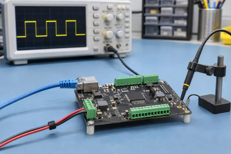
A functional test plan can exercise the intended interfaces within agreed fixture, firmware and acceptance limits. Typical checks may include:
- Power-up: Measure supply rails and current consumption, then check startup status before driving outputs.
- Motion signals: Observe step frequency, pulse width, direction changes and enable behavior under defined commands and receiver conditions.
- Inputs: Simulate home, limit and probe states and confirm that the controller reports the expected changes.
- Spindle and auxiliary commands: Measure the specified analog or PWM output and check relay or auxiliary switching with suitable loads.
- Communications and configuration: Verify the intended host connection and the loaded firmware or configuration revision.
For a two-board product, testing through the mating connection can uncover problems that separate board checks miss. Test coverage needs to be defined for the project; the presence of AOI or X-ray equipment doesn’t establish that a particular functional test was performed. Machine travel accuracy and cutting behavior depend on the drives, motors, mechanics and software working together.
Choosing standard or custom motion hardware
An off-the-shelf motion board can reduce development work when its connectors, I/O and software support fit the machine. A custom assembly gives the equipment designer more control over hardware layout, but requires PCB development, assembly preparation and validation.
| Consideration | Off-the-shelf board | Custom assembly |
|---|---|---|
| Interfaces | Fixed connector locations and I/O allocation. | Circuits and connector positions can follow the machine design. |
| Software | Established software ecosystem, within its compatibility limits. | Firmware and host integration need development or adaptation. |
| Engineering effort | Lower when the board fits the application. | Requires board development, preparation and validation. |
| Installation | May need adapter wiring or mounting changes. | Can be designed around the enclosure, harness and mounting points. |
| Revisions | Product changes depend on the board vendor. | The product owner can manage hardware and BOM revisions. |
| Cost structure | Can suit standard configurations and small quantities. | NRE and tooling need to be weighed against recurring assembly cost. |
A GRBL CNC controller board can be a starting point for a compatible machine. Classic Grbl runs on 8-bit ATmega328P-based Arduino hardware. grblHAL supports a range of other processors, while FluidNC targets ESP32 hardware. The firmware names don’t imply interchangeable processor support.
Mach3 or Mach4 compatibility likewise depends on the motion hardware, firmware and matching host driver or plugin. A USB or Ethernet port alone doesn’t establish compatibility. Wireless connectivity is optional on many systems; its presence doesn’t determine motion precision.
A replacement board can use existing wiring only if the mechanical and electrical interfaces match. Connector pitch, pin assignments, voltage levels, output type and firmware configuration all matter. Similar dimensions or the same axis count aren’t enough. Solder mask color, including black, is a visual choice rather than a motion-control performance rating.
Custom production is most useful when connector layout, mixed-voltage I/O, board stacking or repeated machine builds justify control over the assembly. It doesn’t automatically reduce unit cost or improve machining performance. EBest Circuit’s stated role is to manufacture and assemble the specified hardware using a process suited to its construction.
What to prepare for an assembly build
PCB fabrication and assembly details need to stay aligned: copper weight, finished-hole dimensions, surface finish, panel arrangement and component placement can all affect fit and production. Mixed SMT and through-hole builds may also require selective soldering access. Inspection should suit the package types and distinguish visible-joint checks from hidden-joint checks and functional testing.
For a quotation, the listed inputs include Gerber and drill files, a bill of materials, component placement data, assembly drawings and the required quantity. For stacked boards, include mating connector details. If programming or functional testing is needed, provide the firmware and test requirements as well. Those files and interface specifications establish the intended build far more clearly than a board name or axis count alone.
 AMD Venice Uses 2.5D Packaging to Feed More Bandwidth Into EPYC Zen 6
 Stratasys and Nano Dimension End $42.5 Million Markforged Sale Agreement
 Xometry Q3 2026 Revenue Reaches $252.4 Million as Marketplace Margins Rise