ESP32-P4-PC Demos Add LTE Modem Control and Five Peripheral Checks
New Arduino and ESP-IDF demos pair the ESP32-P4-PC with a UART LTE modem and provide guided checks for five onboard interfaces.

The ESP32-P4-PC now has two software demos aimed at practical evaluation: one exercises a cellular modem over UART, while the other checks five onboard peripherals and reports a result for each. Together, they cover two common engineering tasks: adding a network link where Wi-Fi or Ethernet is unavailable, and confirming that a board’s main interfaces work before it enters a project.

UART demo brings up the LTE modem
The Arduino example connects the ESP32-P4-PC to Olimex’s USB-LTE4G-EU modem over UART. At startup, the sketch probes the modem, disables its sleep mode and reads its identification information, SIM status and signal quality. Once that initial check is complete, a developer can enter AT commands in Arduino Serial Monitor and inspect the modem’s responses.
That sequence makes the demo useful beyond showing that a connection can be made. It gives developers a way to check basic modem and SIM state, observe reported signal quality, and send further commands while working from the serial console. The code and setup details are in the Arduino LTE modem example.
The key hardware detail is the UART voltage mismatch. The modem’s EXT1 UART uses 1.8 V logic, while the ESP32-P4-PC’s UEXT interface uses 3.3 V. Olimex specifies a UEXT-LVL-SHIFT between the interfaces. It plugs into the board’s UEXT connector using a standard UEXT cable; four jumper wires then connect VDD_EXT, GND, TX and RX from the modem’s EXT1 header to the shifter’s low-voltage side. The sketch includes the pinout and setup photos.
The level shifter supports target voltages from 1.65 V to 5.5 V and shifts UART, SPI and I2C signals. Olimex lists I2C operation up to 1 Mbps and SPI/UART operation up to 420 Mbps at 5 V. The board measures 40×22 mm, and its KiCad files are available as open-source hardware. Olimex lists a price of 4.95 EUR.
The USB-LTE4G-EU is based on Quectel’s EG800K-EU and supports LTE Cat 1 bis, with listed maximum rates of 10 Mbps down and 5 Mbps up. Its stated EU band coverage is B1/B3/B5/B7/B8/B20/B28. The modem has USB-C, a nano SIM holder, a U.FL antenna connector and an EXT1 header carrying the 1.8 V UART; its specified operating range is -35 to +75 °C. Olimex lists a price of 11.95 EUR. These details define the intended hardware pairing, while cellular service and antenna arrangements remain part of the deployment setup.
With the modem and level shifter, the board can be used in cellular monitoring, telemetry and industrial IoT designs where wired Ethernet or Wi-Fi isn’t available. The example establishes a control path and demonstrates modem status queries; the application still needs to implement its own data handling and connection behavior.
ESP-IDF demo checks five board interfaces
The second addition is an ESP-IDF board demo that displays board and firmware information on an HDMI monitor at 1280×720 @ 60 Hz, then guides the operator through checks of the main onboard peripherals. Its source code targets ESP-IDF v5.5.5.
- HDMI: checks video output through the LT8912B DSI-to-HDMI bridge.
- microSD: tests a card in native 4-bit SDMMC mode at 20 MHz.
- USB host: checks a USB flash drive on any of the board’s four USB ports.
- Audio: sends a 1 kHz tone to headphones and tests microphone-to-headphone loopback through the ES8311.
- Ethernet: checks the IP101 10/100 interface for link, DHCP and ping.
The interaction is deliberately simple: the BOOT button is the only control. A short press runs the current test; a long press skips it. When the sequence ends, the display and serial console show a PASS/WARN/FAIL/SKIP summary that can be copied into a support request. The result format gives a compact record of which checks ran and how they ended, useful when comparing boards or reporting a fault.
No PC software or test fixture is needed to run the checks. For a basic board evaluation, the ready-made binary can be flashed with esptool. Developers who want to inspect or modify the test logic can build the project from source using ESP-IDF v5.5.5. The distinction is practical: the binary provides a quick check, while the source offers a starting point for adapting the sequence to a particular evaluation workflow.
These demos cover different stages of bringing up an ESP32-P4-PC system. The ESP-IDF program checks local interfaces and reports their status; the Arduino sketch provides a command-level path to an LTE modem, with voltage translation explicitly handled in the wiring. For engineers evaluating the board, the next useful step is to run the peripheral checks first, then verify the modem, SIM and signal readings in the intended cellular setup.
 AMD Venice Uses 2.5D Packaging to Feed More Bandwidth Into EPYC Zen 6
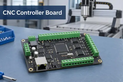 CNC Controller Board Design: Interfaces, PCB Specs and Assembly Testing
 Stratasys and Nano Dimension End $42.5 Million Markforged Sale Agreement