Tantalum Capacitor Selection: Voltage Derating, ESR and Surge Checks
Compare MnO₂ and polymer tantalum capacitors, then check voltage margin, ESR, ripple heating, surge current, polarity and sourcing.
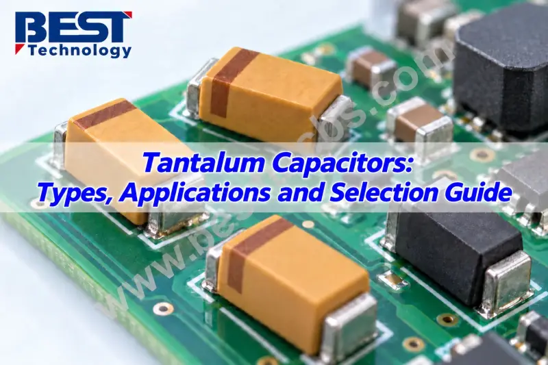
Tantalum capacitors can pack substantial capacitance into a small PCB area while retaining capacitance more consistently under DC bias than Class II ceramic capacitors. That makes them useful for local bulk storage and power rail filtering, provided the circuit can accommodate their polarity and the design accounts for voltage margin, startup current, ESR and heating.
Those engineering checks matter as manufacturers add capacity. At an October 29, 2026 earnings briefing, YAGEO outlined plans to increase capacity for products that include MLCCs and tantalum capacitors by approximately 10%–15%. Some additions are expected in the second quarter of 2027, with others in the second half. The stated plan covers a broader product expansion; it does not specify a 15% increase for tantalum capacitors alone. Nor does added capacity by itself establish inventory or delivery timing for a particular part number.
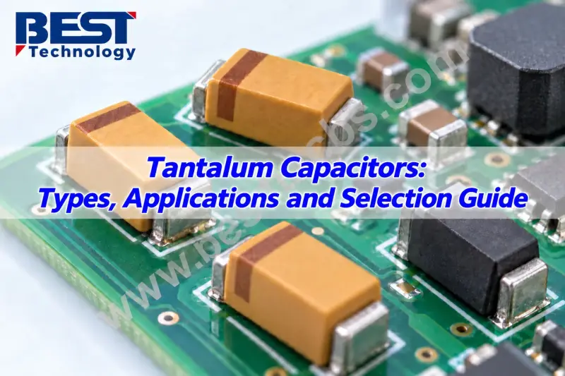
What the component offers
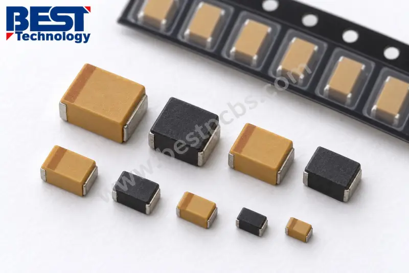
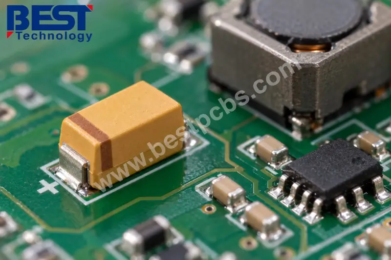
A tantalum capacitor is an electrolytic capacitor. Its anode is made from tantalum, and a thin layer of tantalum pentoxide, Ta2O5, forms the dielectric. In common solid designs, porous tantalum powder creates a large internal surface area. Combined with the thin dielectric, that structure provides relatively high capacitance in a compact package.
The cathode system in common surface-mount solid parts uses either manganese dioxide (MnO2) or conductive polymer. Both types have a defined positive and negative terminal, so polarity must be correct in the schematic, PCB layout and assembly. In everyday comparisons, “tantalum versus electrolytic” generally means tantalum versus aluminum electrolytic; tantalum capacitors are themselves electrolytic devices.
One reason to consider tantalum is its comparatively small capacitance change from DC bias. Class II ceramic capacitors, including X5R and X7R MLCCs, can lose effective capacitance at operating voltage. A tantalum part may therefore deliver a more predictable share of its nominal capacitance in a power rail. That advantage doesn’t settle the choice: frequency response, ESR, temperature, leakage and transient behavior still have to fit the circuit.
MnO₂ and polymer technologies
MnO2 tantalum capacitors are the conventional solid construction. They come in different capacitance values, voltage ratings, package sizes and reliability grades. They can suit DC filtering and energy storage when used within their application limits. Low-impedance supplies and rapid charging deserve particular scrutiny because they can produce substantial surge current.
Polymer tantalum capacitors use a conductive polymer cathode system. Their ESR is generally lower than that of comparable MnO2 products, which can reduce resistive losses in suitable power-filtering applications. Lower ESR doesn’t make polymer an automatic replacement: leakage specifications, temperature ratings, moisture handling and lifetime characteristics can differ between series.
Ripple-current capability and voltage derating depend on the series and operating conditions for both technologies. Wet tantalum capacitors are another category, though the focus here is on solid surface-mount parts commonly used in PCB assemblies. The practical choice is between specific series against circuit requirements, not between two technologies in the abstract.
Where they fit in a power network
Tantalum capacitors are commonly considered for DC rail filtering, local supply support and bulk capacitance where board area is limited. On an MCU control board, for example, a bulk capacitor on the local rail may support longer load-current changes while smaller ceramic capacitors near the processor’s power pins provide low-impedance paths at higher frequencies. The MCU guidance and the full power network determine the values and placement.
A tantalum part may also be used at the input or output of a DC-DC converter if it meets the converter’s requirements. At the input, account for switching current and startup stress. At the output, capacitance and impedance affect ripple, load-transient response and control-loop stability. Some regulators specify an acceptable ESR range; substituting a lower-ESR part can move the circuit outside that range.
Compact surface-mount packages can also suit industrial controllers, communication modules, measurement equipment and selected computing power circuits. In higher-reliability applications—including automotive, medical and aerospace equipment—suitability depends on the exact series, qualification documents, operating temperature, electrical stress and mission profile. An application category alone doesn’t qualify a component.
Work through the electrical limits
Start by defining the minimum capacitance the circuit needs, including tolerance and operating conditions. For a first-order estimate of the voltage change while a capacitor supplies roughly constant current:
ΔV ≈ I × Δt / C
Here, ΔV is the capacitive voltage change in volts, I is current in amperes, Δt is duration in seconds and C is capacitance in farads. An ideal 47 µF capacitor supplying 0.1 A for 100 µs would have approximately 0.21 V of capacitive voltage change. That estimate excludes ESR, inductance, other capacitors and regulator response, all of which affect the real waveform.
Next, establish the maximum voltage the part will see. Include continuous DC voltage, startup overshoot, switching transients, operating temperature and repeated charging conditions. Derating means keeping applied voltage below the part’s rating by a suitable margin; the required margin depends on the technology, series and application. A 10 V-rated part may be a candidate on a nominal 5 V rail, but only after checking maximum rail voltage and transients against that series’ guidance.
ESR contributes to both voltage variation and internal loss. For an ESR-only estimate, use ΔVESR ≈ ΔI × ESR, where ΔI is the current change through the capacitor. For sinusoidal ripple, RMS current multiplied by ESR gives the ESR-related RMS voltage component. Keep peak, peak-to-peak and RMS values distinct. Total impedance also includes capacitive and inductive behavior, so assess impedance over the frequencies that matter to the circuit.
Ripple current heats the part. A first-order estimate of resistive loss is P ≈ IRMS2 × ESR. Use ESR at the relevant frequency and temperature. If ripple contains several significant frequency components, assess their losses rather than assuming one ESR value describes the full spectrum. Compare the resulting losses and temperature rise with the manufacturer’s ratings and application guidance.
Startup conditions need their own review. Connecting a discharged capacitor rapidly to a low-impedance source can create a large charging current. Check the startup waveform, source impedance, current limiting and repetition rate. A part can be below its voltage rating in steady state and still face unacceptable stress at power-on, particularly at hot-plug inputs or directly connected power sources.
Check the package, polarity and process
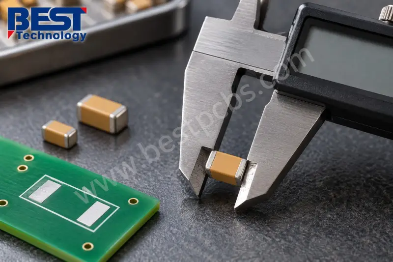
Use the selected manufacturer’s drawing and recommended land pattern to verify body length, width and height, terminal dimensions, pad geometry, orientation, clearance and access for inspection or rework. A matching case designation doesn’t remove the need to check the actual dimensions.
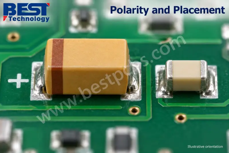
Confirm polarity from the documentation for the exact series. Marking conventions vary; don’t infer the positive or negative terminal from a stripe without checking. The PCB assembly drawing should agree with the component marking. Assembly documentation should also cover the permitted reflow profile, storage and moisture handling where applicable, cleaning restrictions and rework limits.
For a control board with a nominal 5 V supply seeking local bulk filtering, 47 µF might be an initial capacitance target. That alone cannot approve a part. The maximum rail voltage and transients still need to be established; rated voltage must follow the derating review; ESR must suit the regulator and load transients; and temperature, package height and assembly process must meet the product requirements. Candidate datasheets should be compared, then startup, load transients, ripple and temperature validated on the design.
Substitution with MLCCs
Tantalum capacitors can replace MLCCs in some circuits, but matching nominal capacitance and rated voltage doesn’t establish interchangeability. Tantalum parts are polarized, while MLCCs are generally non-polarized. Class II MLCCs can lose effective capacitance under DC bias; tantalum parts usually show less change. ESR depends on the tantalum electrolyte and series, while MLCCs are typically low ESR and often suit high-frequency local decoupling.
Each technology brings different checks. For tantalum, review surge current, voltage margin, leakage and polarity. For an MLCC, assess effective capacitance, dielectric, package and mechanical stress. A common power network uses both: bulk capacitance supports the rail while smaller ceramic parts handle local high-frequency decoupling. Before substitution, check effective capacitance, impedance, regulator stability, polarity, footprint and reliability requirements. The MLCC selection guide provides more background on ceramic capacitor choices.
Procurement and capacity plans
YAGEO identified AI applications as a demand driver for MLCCs and tantalum capacitors at its October 2026 briefing and outlined phased capacity additions during 2027. For buyers, an expansion plan passes through equipment installation, production ramp-up and product-specific availability before it can support a purchase order. Demand growth for selected products doesn’t establish a shortage across every capacitance, voltage rating and package. Planned capacity isn’t current inventory, and it doesn’t determine the price or delivery terms of each part.
Anchor purchasing decisions to the full manufacturer part number. Confirm manufacturer and series, complete ordering code, electrical limits, package and polarity, temperature requirements, qualifications or screening, orderable quantity, minimum order quantity, delivery schedule, quotation validity, traceability documentation and packaging format. Review alternatives before a production schedule depends on one source. A distributor listing is useful only when the offered component matches the approved requirement; engineering review should precede substitution, and a controlled bill of materials may also require customer approval.
Failure checks and assembly support
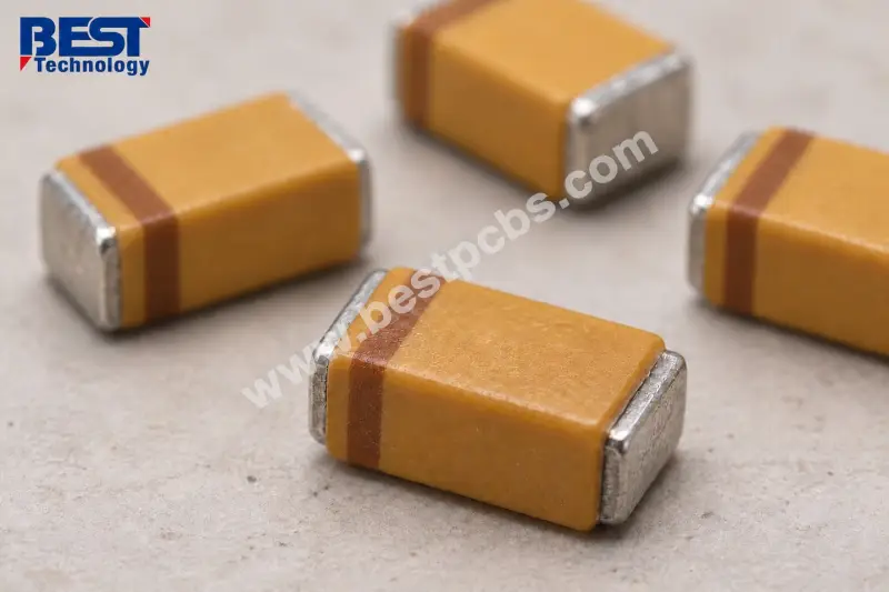
Many molded surface-mount tantalum capacitors mark the positive terminal with a band or other indicator, but conventions vary. Confirm the exact series documentation and match it to the assembly drawing; don’t assume every stripe marks the negative terminal.
Hot-plug use requires review of voltage overshoot and charging current, along with the series, source impedance, protection and startup conditions. Replacing MnO2 with polymer may be possible, but differences in ESR, leakage, ripple capability, voltage requirements, environmental behavior and dimensions need evaluation.
For a suspected failed part, disconnect power and discharge the circuit safely before investigation. A low-resistance reading on an assembled board doesn’t identify the capacitor by itself because parallel circuitry affects the measurement. Diagnosis may require isolating the part and measuring capacitance, ESR or leakage under controlled conditions.
Apparently similar part numbers can differ in electrolyte technology, ESR grade, tolerance, voltage, temperature rating, qualification, surge screening, dimensions or packaging. Matching capacitance and rated voltage alone leaves significant requirements unchecked. Tantalum capacitors remain useful when their compact bulk capacitance and DC-bias behavior suit the circuit; reliable selection and procurement both depend on the exact approved series and its operating conditions.
 AMD Venice Uses 2.5D Packaging to Feed More Bandwidth Into EPYC Zen 6
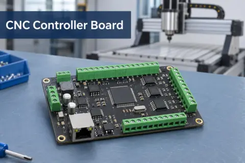 CNC Controller Board Design: Interfaces, PCB Specs and Assembly Testing
 Stratasys and Nano Dimension End $42.5 Million Markforged Sale Agreement