Prelta PS4395 and PS5395 Relays Add Adjustable Current Trips and Delays
Prelta’s AC and bipolar DC relays combine selectable current ranges, adjustable trip delays and three output types for equipment monitoring.
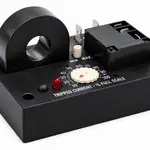
Current monitoring becomes more useful when a trip can be matched to the equipment’s normal operating range and response time. Prelta Systems’ PS4395 and PS5395 protective relays provide adjustable trip settings for AC and bipolar DC applications, respectively, with several choices for switching an external circuit. That combination gives a designer control over two separate decisions: when the relay reacts, and how its output signals the rest of the system. The product details don’t establish how either model performs in a particular installation, so those settings still need to be checked against the load and control circuit.

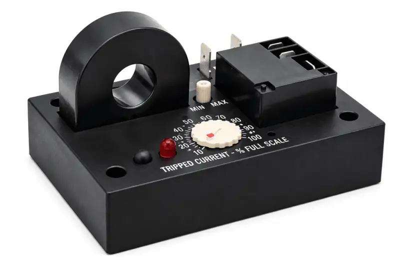
AC and bipolar DC coverage
The PS4395 monitors AC current from 1A to 100A at frequencies between 60Hz and 400Hz. The PS5395 is intended for bipolar DC current and offers four selectable measurement ranges: 1-10A, 3-30A, 6-60A or 10-100A. That division gives designers separate models for AC and DC sensing while retaining a similar approach to setting the trip response. It also means that selecting a model starts with the kind of current in the circuit, followed by the expected operating range.
Both units monitor current flowing through a conductor. When the measured current crosses the selected threshold—rising above it or falling below it—the relay changes its output state. This makes the devices applicable to monitoring loads such as motors, pumps, fans and heaters, where an unusual current level can serve as a signal to trigger an external response. The relay can therefore act as one part of a larger control arrangement: the current change is detected locally, while the connected circuit determines what happens next.

The threshold and delay settings let an engineer tune when that response occurs. A delayed transition can help avoid reacting immediately to a brief change in current; the appropriate setting depends on the behavior of the monitored load and the response expected from the connected control circuit. The supplied specifications list selectable on-delay options of 0.5-6 seconds, 2-25 seconds, 0.1-1 second, or no delay. The available delay ranges are stated for both models. That range of timing choices gives the designer room to account for different operating behavior, but the product information doesn’t explain how each setting should be paired with a particular type of load.
For example, a control scheme that needs to respond to a sustained current change may call for a different delay from one that must react promptly. That’s a system-level decision, not a setting that can be chosen from the relay’s range alone. If you’re working in this space, the practical question is whether the threshold and delay distinguish a meaningful fault or operating change from normal variation in the equipment.

Three ways to switch an output
Each relay offers three output types: a 20A single-pole double-throw (SPDT) relay, an opto-isolated NPN transistor, or an opto-isolated zero-crossing triac. The SPDT contact is rated for 20A in the normally open configuration and 10A in the normally closed configuration at 240V AC with a resistive load. Those figures describe a specific contact arrangement and load condition, rather than a general rating for every way the relay might be used.
Those options suit different control interfaces. The mechanical SPDT contact provides a changeover connection, while the transistor and triac outputs provide opto-isolated solid-state switching. The triac’s zero-crossing operation is specified as an output feature, but the supplied details don’t state switching limits for the transistor or triac. Designers should check the relevant output ratings and load requirements before choosing an interface. The choice can affect how the relay connects to downstream control equipment, so it belongs in the design review alongside the sensing range.
The SPDT ratings are specific to a 240V AC resistive load. They shouldn’t be treated as ratings for other load types or operating conditions. Motor and other inductive loads, for example, have different electrical characteristics from resistive loads, so the output’s suitability needs to be assessed against the actual application. The stated rating is useful, but it doesn’t answer every switching question.
And the output choice isn’t just a matter of convenience. A mechanical contact and a solid-state output behave differently as interfaces, and the product information gives only limited detail for comparing their electrical limits. The numbers here are underwhelming as a full selection guide; they’re a starting point that leaves application checks to the designer.

Sensor aperture and larger conductors
Both models include an internal current sensor with a half inch aperture. For installations where the monitored conductor is too large for that opening, Prelta says remote transformers can be used. This gives the range a way to accommodate larger conductors while retaining the relay’s current-monitoring function. In practice, the sensor arrangement is one of the early fit checks, since the conductor must be compatible with the chosen sensing method.
The practical fit depends on the conductor, selected current range, supply and output interface, as well as the required trip point and delay. Those details determine whether a relay can be integrated into a particular monitoring or control arrangement. The available product information specifies the sensing ranges and output choices, but doesn’t provide further installation, environmental or accuracy figures. That leaves important implementation questions for the full product documentation or a direct check with the manufacturer.

Remote transformers add another element to consider: the designer needs to confirm that the sensing arrangement and selected relay range suit the intended measurement. The source details don’t specify transformer models or configuration guidance, so no particular setup can be inferred. A fit check first. Then the trip behavior and output can be assessed in the context of the equipment being monitored.
What the specifications mean for a design
For equipment designers, the useful distinction is the combination of current range, timing and output type: the PS4395 covers AC from 1A to 100A over 60Hz to 400Hz, while the PS5395 targets bipolar DC across four selectable ranges up to 100A. Checking those parameters against the load and control input is the next step in deciding whether either relay fits a monitoring design. This is more significant than it looks: a current relay’s value depends on how well its trip behavior matches the system around it, not simply on the maximum current listed in a specification.
Similar monitoring systems typically need their sensing threshold, delay and output interface considered together. A suitable current range won’t by itself establish that a relay will respond as intended, and a suitable output type won’t resolve uncertainty about the load or installation. Here’s the thing: the product details offer a concise set of selection parameters, but they don’t replace application-specific checks. That said, the separate AC and bipolar DC models and the choice of three output types give engineers a clear basis for narrowing the options.
What this means for you is that the model choice should follow the current being monitored, while the output and delay choices should follow the control task. The source doesn’t supply accuracy, environmental or detailed solid-state output ratings, so those points need further confirmation before a final design decision. For equipment using motors, pumps, fans or heaters, the relevant load behavior and the response expected from the connected circuit deserve particular attention (and this is the part most people overlook).
Product details are available from Prelta Systems.
 AMD Venice Uses 2.5D Packaging to Feed More Bandwidth Into EPYC Zen 6
 CNC Controller Board Design: Interfaces, PCB Specs and Assembly Testing
 Stratasys and Nano Dimension End $42.5 Million Markforged Sale Agreement