CMM Inspection for CNC Parts: Dimensional Checks and Reports
CMM inspection measures critical dimensions and geometric tolerances, with reports that document results for prototypes, small batches and repeat production.
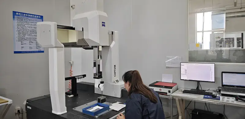
What coordinate measurement adds to CNC inspection
Coordinate measuring machines (CMMs) can check dimensions and geometric relationships across complex machined parts using a shared three-dimensional reference. That makes them useful when a drawing calls for many critical features, tight tolerances or positions that are difficult to verify with conventional measuring tools.
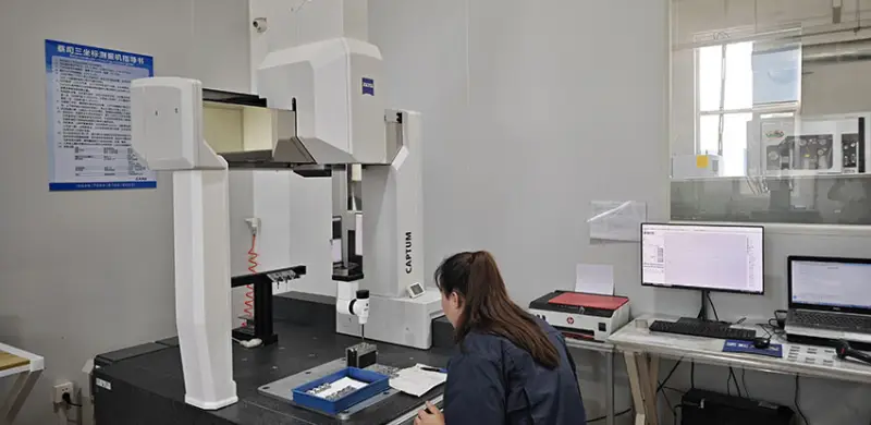
A CMM records points on a component’s surface and analyzes them to assess feature size, shape and location. Depending on the equipment and method, measurement uses a contact probe or a non-contact sensor. Contact probing is widely used for machined metal parts, including holes, slots, steps and surfaces.
The practical advantage is a systematic measurement of multiple features within one coordinate system. That can make it easier to evaluate relationships across a part than checking each feature separately with manual tools. The measurement strategy, equipment and software still need to suit the drawing requirements; a CMM’s capability depends on those choices.
Why dimensions and geometry both matter
CNC machining can produce precise parts, but actual dimensions can vary with tool wear, material properties, thermal expansion, machine condition and workholding. CMM results can be compared with the nominal dimensions and tolerance limits on the applicable drawing to check features such as hole diameters, center distances, step heights and surface locations.
Size alone doesn’t determine whether a component will assemble or function as intended. Flatness, perpendicularity, parallelism, position and profile can also matter. Where the equipment, software and measurement plan support the specified geometric dimensioning and tolerancing (GD&T) characteristics, a CMM can evaluate these relationships and flag deviations that simple size checks may miss.
That distinction matters on parts with intersecting features, angled faces, irregular outlines or other three-dimensional geometry. Manual checks can take time and may vary with the operator or setup. A CMM can establish a coordinate system and assess selected features in a consistent setup, including on precision housings, brackets, automotive parts, aerospace components and custom-machined parts with complex drawings.
Finding deviations before assembly
A dimensional or geometric error can create interference, excess clearance or misalignment. In an assembled product, those conditions may contribute to vibration, wear or reduced performance. Measuring parts before shipment gives the manufacturer and customer data to assess conformity and address deviations before they reach a production line.
Those results can also help when investigating a manufacturing issue or refining a machining process. Identifying a problem earlier may limit rework, scrap, replacement costs and downstream delays. The measurement report provides evidence for that discussion: actual readings can be reviewed against specified criteria instead of relying only on a general pass statement.
What an inspection report can show
Report content depends on the drawing, inspection plan, software and customer’s requirements. It may identify the part number, drawing number and revision; list actual readings for selected dimensions; and show nominal values and tolerance limits. Where applicable, it can include GD&T results for characteristics such as position, flatness, perpendicularity or profile, along with a pass/fail assessment against the stated acceptance criteria.
Reports may also record the measurement date, equipment identification and other traceability details. The requested scope can range from a full dimensional report to results for a defined set of key characteristics. Customers should specify which features matter and what format they need, since a report is only useful for review when it addresses the relevant drawing requirements.
Matching inspection scope to production
CMM measurement can support prototype, small-batch and recurring production work, but the appropriate scope varies. On a prototype, it can check whether the first manufactured part meets the drawing before the design proceeds or further parts are made. For small batches, it can document critical features on custom components. In repeat or larger production, it can support first-article checks, process verification and quality investigations.
Sampling frequency and the number of features measured depend on the part’s risk, the production process and customer requirements. A full CMM inspection isn’t necessary for every component: simple parts may be adequately checked with calibrated conventional instruments, while complicated geometry and demanding tolerances can justify coordinate measurement. Choosing the method and scope involves balancing measurement needs, inspection time and production cost.
Preparing a useful measurement plan
Customers considering a CMM report should raise the request for parts with tight tolerances, critical hole positions, several datum relationships, complex geometry or documentation requirements. First-article samples, prototype validation, supplier qualification and components for precision assemblies are also common reasons to request documented measurements.
Providing the latest engineering drawing, identifying critical-to-quality features and specifying the reporting format before production helps the manufacturer plan the inspection. Any applicable standard or customer-specific procedure should be communicated at that stage as well. With those inputs, the measurement plan can focus on the features the customer needs to evaluate.
Machining and measurement in one workflow
SANS Machining offers CMM inspection for precision-machined components and can provide reports according to project requirements. Its stated range includes aluminum parts, stainless steel components, brass fittings, precision housings and other custom-machined products. The inspection method can be discussed in relation to the drawings, tolerances and intended application.
For customers, the key is to define the required evidence alongside the part requirements. A drawing, a list of critical features and a clear report request give the manufacturer a basis for machining and dimensional verification, and give the receiving team measured results to assess before assembly.
 AMD Venice Uses 2.5D Packaging to Feed More Bandwidth Into EPYC Zen 6
 CNC Controller Board Design: Interfaces, PCB Specs and Assembly Testing
 Stratasys and Nano Dimension End $42.5 Million Markforged Sale Agreement